The purpose of this page is to show you how to take apart the peripheral expansion box. There may be several reasons why you would want to do so:
Malfunction symptoms
_Finer diagnostic
Opening the PE-box
_Cable connection card
_Disk drive
Cleaning the bottom connectors
Changing the mains voltage
Fixing the power supply board
Fixing the transformer
No power at all
The fan doesn't work, but everything else is ok.
The fan works but nothing else does: no lights appear on any of the cards, the disk drive doesn't spin at power up.
The card lights go on, but the disk drive does not spin / its red light
does not lit upon disk access.
Random malfuntion of several cards
Get a voltmeter and measure voltage accros the silver part of the bottom plate and slot connections number 1 (the first at the rear), 57 and 59. (the last two at the front). Either side of the slot is ok, since power always comes through two opposite pins (i.e. 1+2, 57+58, 59+60).
You should get:
2 ------------------------------ 60 Front
1 ------------------------------ 59
  |                           ||
 +5                        -12 +12
All voltages will be lower if cards are still present inside the box (approx +8, -16, +16V) than in a bare PE-box (+13, -25, +25V). This is normal.
After removing the disk drive (see below), check
the
voltage on the "molex" connector, between any of the center connections
and the side ones. You should read +5 volts on one side and +12 volts
on
the other.
 _________
| O O O O |
  \/  \/
 +5  +12
First of all, unplug the power cord and store it away in a locked drawer. We're talking at least 100 volts upstream of the mains switch and this is not something to take lightly: it could easily kill you. So take no risk and make sure the PE-box is not connected to the wall power until it's fully reassembled. You have been warned. If you kill yourself, don't come and complain to me!
To remove the cable connection card, you will need to unfastened the brace that fixes it to the back of the PE-box (one screw).
If you want to clean this card, remove the two handles (pull them apart) and the four screws that lock the metal case. The label can stay and will serve as a hinge. Take the card out and clean the connections at the place they fit into the slot at the bottom of the PE-box. A toothbrush dipped in baking soda (sodium bicarbonate) will do. You might also use a "scrotch-brite" scratchy sponge, or even very fine sandpaper. In any case, make sure not to touch the contacts with bare fingers after you are done, as skin oils will promote oxidation.
If you determine that there is a problem with this card, or with the 'firehose' connection cable, refer to my PE-Box page for instructions on how to fix it.
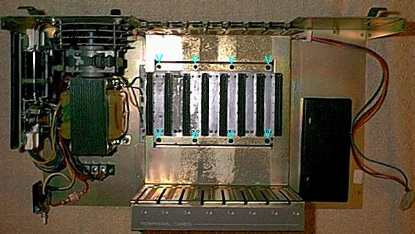
To remove the disk controller card, it is best to first pull out the drive. There are two screws, in slotted holes, under the PE-box (cyan arrows in this picture), and two more on top of the drive under the PE-box lid (see this picture). Remove them and gently pull out the drive, without putting too much strain on the cables.
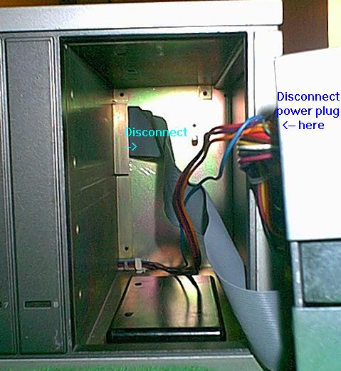
Now reach inside the hole and disconnect the flat cable from the card connector, at the very bottom of the drive compartment. Here's a picture. Then disconnect the drive power cord and store the drive in a safe place.
Now you can remove the controller card and clean it as described above.
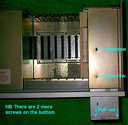
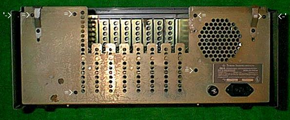
Grab your screwdriver and start removing the screws that hold the box closed. There are plenty: 7 at the bottom (picture), 6 at the back, and one on each side (picture).
Pull out the mains push-button from the front panel (if so equiped). Then gently slide out (foward) the front-and-side part of the box from the bottom-and-back. See this picture.
Remove the screws that hold the 8-slot bottom plate in place (picture). Together with it will comes the metal guide that insures each card slides properly in place.
The connector plate is a very simplistic PCB: it just connects every line between eight 60-pin card edge connectors. Four power supply lines are attached to it, that go to the power supply board. This is unregulated power, to be used by voltage regulators installed on cards. See this picture.
You can clean the connectors with an old toothbrush diped in a solution of baking soda (sodium bicarbonate). Rince with distilled water, shake the water out and dry thouroughly (e.g. overnight) before attempting to use.
If you suspect one trace is broken, locate it and bridge the gap with solder.
Now is a good time to dust off the rest of the box, particularly the fan, and the transparent plastic things that lead the light from the card LEDs to the front panel...
The "new" PE-boxes, those with a rocking mains switch, have a rotatory selector that lets you pick up the desired voltage. The older models, those with a mains push-button, don't have such a selector even though the transformer can often accept the same range of voltage.
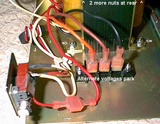
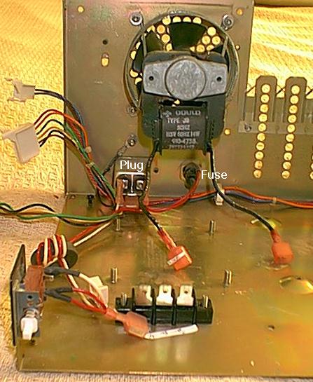
If you look at the transformer, you will see that its primary (at the base of the transformer) has five power wires, plus two for the fan. One is common to all voltages (white, soldered to the mains switch), one is connected to the mains switch (red for US power), the other three are parked on an isulating pad (brown, orange, and black). See this picture.
To use your PE-box with another voltage, simply exchange the red wire for the one corresponding to your local wall-power voltage. Unfortunately, I don't know for sure which color corresponds to which voltage (if you figure it out, let me know). From the order the wires come out of the transformer, and by measuring the AC voltage on the three spare wires when the tranfromer is powered by the red one, I was able to make the following guess: Black = 100 VAC, Red = 115 VAC, Brown = 220 VAC, Orange = 240 VAC. But remember this is only a guess...
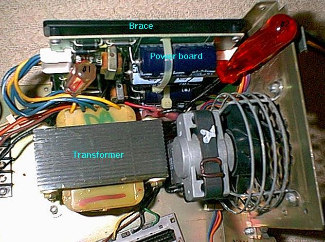
The power-supply board is mounted on a plastic brace that holds it vertical, along the left side of the PE-box. To remove this brace, unfasten the two screws that fix it to the base of the box (see this picture: follow the screwdrivers), then slide it off towards the left side.
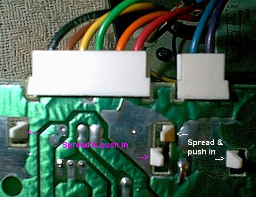
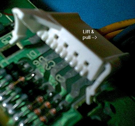
Disconnect the three sets of wires. All connectors are built on the same model, with self-locking clamps that fit into holes in the board (see picture). To remove them, flip the board over, spread the two clamps to release them, and push them into their holes. The plug should now be tilted up (see picture), and it's a simple matter to pull it out. To put it back, install it at the same angle, them push the clamps down into the holes.
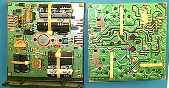
It's easier to work on the board if you remove the plastic brace, not to mention that there are two components under the board, hidden by the brace (purple arrows in this picture). So remove the 4 screws that hold it in place. As the board is perfectly square, make sure to mark which side goes where on the brace (if you forgot, refer to the above picture).
The +5 volts regulator is the flat 3-legs thing labeled 7805. The +12 volts regulator is the big silver eye-like thing in the middle, they are labelled in cyan in the above picture.
Desolder and replace them with a similar part. Or possibly with one that gives out more current so you can power both a hard-drive and a floppy (I haven't tried that).
The transformer is bolted to the bottom of the box with 4 bolts that are welded in place (two of which are visible in this picture). Use a wrench (or pliers) to remove the 4 nuts, then gently lift up the transformer. It will remain attached to the mains switch by at least the white wire, but that's ok. Here's a picture with the transformer removed, in which you can see the 4 bolts protruding from the bottom of the PE-box.
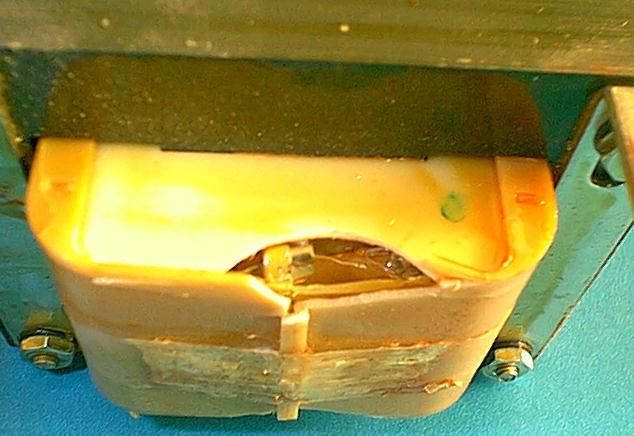
The fuse is hidden inside the transformer's white plastic case. As it is hopelessly glued together with resin, the best way to access this fuse is to break a hole inside the plastic, at the bottom of the transformer, opposite the wires. See this picture.
There is no fuse holder, as a matter of fact it may be that the fuse is just a thicker portion of wire. Thus, if you want to install a new fuse, you will have to solder one in place. In this respect, buying fuses that have axial leads will help.
I don't know for sure what's the rating of this fuse. The writing was hard to read on mine, and all I could decipher was 12A / 250V. Which seems like an awfull lot (3 kilowatts???). So maybe it's 1.2A ? In doubt, I put in a 7A fuse and it worked. Of course, maybe the transformer is gonna fry next time I accidentally short +12V with -12V, as I've been known to do...
To install a new transformer, you will need to desolder the white wire from the mains switch, then solder back the new transformer. Make sure you insulate your work with electrical tape, real well: we don't want to shortcut these two terminals!
Then connect all the wires, including the "unused" ones that should be parked on the dedicated terminal.
Go get the power cord and plug it in. Turn power on and check if all the required voltages are present where expected (see above). If so, turn power off and proceed.
Test your system. If it works fine, install the remaining cards and enjoy. If not, start over... or buy another PE-box.
Preliminary 7/3/02 Not for release Revision 1 8/27/02 Added pictures. OK to release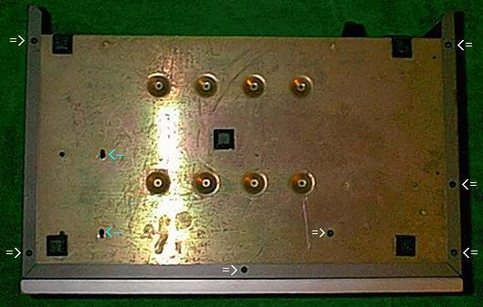