Texas Instruments originally marketed a pair of pretty crude joysticks. Each consists in four switches arranged all around the stick. By pushing the stick towards a switch you can close it. By pushing it on the diagonal between two switches you close both of them. This gives you eight possible joystick positions (nine, if you count the center). In addition, each joytsick has a unique pushbutton that serves as a "fire" trigger.
                  ___________
                 ( 1 2 3 4 5 )
                  \ 6 7 8 9 /
# I/O Use          \_______/
- --- -------
1     not used
2  >  Test joystick 2
3  <  Up
4  <  Fire button pressed
5  <  Left
6     not used
7  >  Test joystick 1
8  <  Down
9  <  Right
As you can see, each joystick has its own input pin (#2 and #7), but
the
output of the switches as the fire button are common to both joysticks.
In fact, the original TI joystick had each a cable connected to a
common
plug. Later on, other companies marketed fancy looking joystick that
and
one plug each, but this meant that only one stick at a time could be
used
(which is OK most of the time).
Joysticks are accessed with the same 74LS156 decoder that performs the selection of a column on the keyboard. Selecting column 6 activates joystick 1, and column 7 activates joystick 2. The output of the decoder is amplified through a transistor, so as to produce a stronger signal for the joystitcks. A non-selected joystick is connected to +5V through the transistor, a selected joystick is connected to -5V (although the effective output voltage is about -0.5V at the joystick port).
The five outputs are read together with the first five keyboard rows. This is very infortunate since the last one is also used by the alpha-lock key. When the alpha-lock key is down it sources so much current that the joystick "up" switch appears to be constantly close. As a result, the "up" function is permanently on for both joystick when the alpha-lock key is down. That was especially stupid of the TI designers, since there were 3 more keyboard rows that could have been used for the alpha-lock key (or combine it with the fire buttons: this may have been usefull for continuous fire).
TMS9901 |
The keyboard column selector is controled by CRU bits 18-20 (put >0024 in R12) in the CRU address space of the TMS9901. The joysticks read back at bits 3 to 7 (CRU address >0006).
| Column:
R12 address |
6 |
7 |
|---|---|---|
| >0006 | Fire | Fire |
| >0008 | Left | Left |
| >000A | Right | Right |
| >000C | Down | Down |
| >000E | Up | Up |
* This routine reads the status of joystick 1 JOY1 LI R12,>0024 CRU address of the column decoder TB -11 Quick test for the fire button LI R12,>0006 CRU address of the keyboard rows SK1 SLA R1,2 Joystick is left, now test vertical position SK2 SLA R1,2 Joystick is right, now test vertical position |
The drag with TI joysticks is that they only return up/down/left/right yes or no informations, which limitates possible moves to 8 directions. PC joysticks on the other hand are analog, i.e. they have two variable resistors, one in the vertical axis, one in the horizontal axis. The current value of these resistors indicates how far the joystick was pushed.
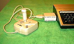
This page describes a small adapter board that I designed a few years ago. It allows to connect PC joysticks to the TI-99/4A joystick port. Of course, you'll need a special software to use them. I wrote several programs to this end, that can be downloaded from this site. These programs are also described below.
Building a joystick adapter
Circuit description
Components list
Connectors wiring
Buiding the adapter board
Modifying the joysick port
Related software
Joystick driver
Automatic sprite linking
Calibration program
TI-Artist drivers
The principle of this adapter is to convert the value of the joystick resistor into a time: this is archieved by a chip called 74LS221. This chip contains two "one-shots", i.e. circuits that, once triggered issue a pulse whose length is depending upon an external capacitor and an external resistor. You probably already understood that the resistor will be the joystick itself.
The pulses (one for vertical excursion, one for horizontal) are then fed into the joystick port: all the TI has to do is to time them, which is easily archieved by an assembly language driver.
This leaves 3 available connections in the joystick port, that we can use to return joystick buttons status: right, you can now have 3-buttons joysticks!
The adapter board could be powered by a small battery, but I found easier to modify the joystick port, so that the two currently unused pins (#1 and 6) now provide groud and +5 Volts respectively. This console modification is really very easy to do and results in a much more convenient board, thus I think it's worth doing it.
Note that this scheme describes a board designed for use with a single joystick. For the second joystick, duplicate the circuit and use the connector numbers indicated in parenthesis.
P1-P9 refer to the console 9-pin joystick port.
J1-J15 refer to the joystick 15-pin connector.
R1 1K |
In this schematic, the +5V power is supplied by the console via P6, whereas P1 is connected to the console ground. You may use a battery instead but you still need a common ground connection with the console.
When the software tests the joystick, P2 (or P7) shifts from high to low, which blocks T1. The basis of T2 can now be driven by R1 and T2 becomes passing. (This amplification circuitery is required since pressing a key drags so much current that the interface board would not be triggered if a key is pressed).
The three joystick buttons are now connected to ground, via D1 and
J4
(or J12). The diode is required to avoid interference whith keyboard
scanning.
When button 1 is pressed the ground appears on J2 (or J10) and is
feeded
into P4 (i.e. "joystick fire").
Button 2 connects J7 (or J14) to ground, feeding it into P9 (i.e.
"joystick
right").
Finally button 3 is fed into P3 (i.e."joystick up"). Unfortunately,
having only a 2-buttons joystick I don't know which joystick pins are
used
by the third button. You'll have to check it yourself if you have a
3-button
joystick. Otherwise, you may decide to install a pushbutton of your own
on the board.
Second, the low signal from T2 also triggers both "one-shots" in the 74LS221, via their A* inputs. Note that the B and Clr* inputs are held high via R2.
The lenght of pulse in the first half-chip is determined by C1, R3 and the joystick vertical resistor, accessed via J6 (or J13). The output Q is used to drive T3 via R5 and make it passing. This grounds P8 (i.e. "joystick down") via R6, which is required to avoid interferences with the keyboard.
Similarly, the pulse length of the second half-chip is determined by C2, R4 and the joystick horizontal resistor, accessed via J3 (or J11). The pulse is fed into T4 by R7, wich connects P5 (i.e. "joystick down") to the ground, via R8.
The other end of both joystick resistors are connected to +5V via J1 (or J9).
Note that R3 and R4 are required to avoid a null resistivity when the joystick is pushed fully up/left.
Note: this scheme is valid for joystick resistor varying from 0 to 150 KOhms. If yours have different values, you may have to play with C1/C2 and R3/R4 until you get pulses of suitable length. Use option 2 of the calibration program to determine optimal values.
For each joystick you need:
All this should cost less than $5
In addition, you need connectors:
Each connector costs $2 to $3.
| Adapter board | Console port | Joystick plug | (Second joystick plug) |
|---|---|---|---|
| Ground | P1 | . | . |
| T1' basis (joy 2) | P2 | . | . |
| . | P3 | ? (both buttons 3) | ? (button 3 on joy 2) |
| . | P4 | J2 + J10 | J2 |
| R8 (joy 1) + R8' (joy 2) | P5 | . | . |
| +5V | P6 | J1 + J9 | J1 |
| T1 basis (joy 1) | P7 | . | . |
| R6 (joy 1) + R6' (joy 2) | P8 | . | . |
| . | P9 | J7 + J14 | J7 |
| R4 (joy 1) | . | J3 | . |
| R4' (joy 2) | . | J11 | J3 |
| R3 (joy 1) | . | J6 | . |
| R3' (joy 2) | . | J13 | J6 |
| D1 (joy 1) | . | J4 | . |
| D1' (joy 2) | . | J12 | J4 |
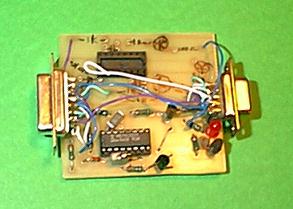
The circuit is so simple that you would not even need to etch a PCB for it, nevertheless it's cleaner so may be it's worth doing it... it's up to you. On my part, I etched a 6x6 cm board, handling 2 joysticks and fitting exactly in a small 6x6 cm box I had at hand. It plugs directly into the console port.
I would advise you to use sockets for the 74LS221, so that you can easily change it, if you suspect it has been damaged with time.
The buttons connections don't need to be etched: you can just place a wire between joystick and console connectors.
The LED is optional, I just added it for the fun of seing which joystick is currently accessed, if any.
You may have to modify capacitors values after you checked your board with the calibration program. It may even be necessary to add up two capacitors (for instance 100 uF and 10 uF) by placing them in parallel. When designing your PCB, plane pads for extra capacitors, just in case.
In case you decide for a 4.5 V battery (and switch), remember that you still need a common ground with the console. For instance you could pass a piece of wire through the PEB cable port (make a little notch in the console wall, so that you can still connect the cable). The wire can be fixed to one of the small screws you see inside this port.
However I would advice you to modify you console so that groud and
+5V
are available through the currently unused pins of the joystick port.
This
only takes a few minuts and avoids the burden of a battery, not to
mention
the fact that it may be used by future devices connected to the
joystick
port (such as a drawing pad for instance).
+---------+ |
Here is a picture for you.
The following programs are provided on the accompanying disk:
Joystick driver
Extanded Basic usage
Assembly usage
Automatic sprite linking
Extended Basic usage
Assembly usage
Calibration program
Extended Basic program
Direct access from
Extended Basic
Direct access from Assembly
TI-Artist drivers
TI-Artist version I
TI-Artist Plus!
Calibration program
This is the file called PC-JOY/DRV, a DF80 file that can be used both with extended basic and with assembly programs. A special loading "trick" prevents the REFs to cause errors when loaded from extended basic.
Load the driver with:
CALL INIT
CALL LOAD("DSKx.PC-JOY/DRV")
You can then call four different subroutines
Position mode
This subprogram is intended to map joystick position position to screen, it thus returns vertical values from 1 to 192 and horizontal values from 1 to 256.
CALL LINK("JPOS",joynb,vert,horiz,fire)
Joynb is the joystick number 1 or 2. You may use -1/-2 to
modify
vert range. Other values issue a 'bad value' error.
Vert is a number between 1 and 192. Or between 1 and 256 with
negative
joystick number.
Horiz us a number between 1 and 256.
Fire is an optional parameter, returning fire buttons status.
This
is a number between -64 and +64. See JFIRE subprogram for details.
Speed mode
This subprogram is intended to translate joystick position into a speed, a strength, etc. Thus both vertical and horizontal values range from -128 to 127.
Since it may be difficult to precisely center the joystick (in oder to get null speed) a small area, around central position returns 0 even if the joystick is not perfectly centered.
CALL LINK("JSPEED",joynb,vert,horiz,fire)
Joynb is the joystick number 1 or 2. Using negative numbers
(-1/-2)
disables the central "stillstand" area: 0 is only returned when
the joystick is perfectly centered.
Vert is a number between -128 and 127. The 0 value is returned
when
the joystick is close to center, even if it's nox exacltly centered.
Horiz is a number betweem -128 and 127. Here also a small area
returns
0 (unless a negative joystick number was used).
Fire is an optional parameter, returning fire buttons status.
This
is a number between -64 and +64. See JFIRE subprogram for details.
Crude values
This subprogram just returns crude timing values. Their range thus depends on the characteristics of your joystick and interface board. Therefore I would not recomend using this routine for anything else than test purposes.
CALL LINK("JTIME",joynb,vert,horiz)
Joynb is the joystick number 1 or 2.
Vert is the crude timing value for the vertical axis.
Horiz is the crude timing value for thr horizontal axis.
Fire buttons
This subprogram is intended to quickly test fire buttons status on both joysticks at once (although it could well be used with a single joystick).
CALL LINK("JFIRE",Fire1,Fire2)
Fire1 is the fire buttons status for joystick 1.
Fire2 is the status for joystick 2
The status is coined by adding up the following values:
1 for button 1
2 for button 2
4 for button 3
Thus, pressing all buttons together retuns 7 (1+2+4), whereas none returns 0.
In addition these values can be modified by using some keyboard keys,
this
is especially usefull if your joystick has only one button. Provided at
least one button is pressed the following values are added:
8 for <fctn> key
16 for <shift> key
32 for <ctrl> key
Thus <shift>button1 is 17, whereas <ctrl><shift>button2 is 50, etc.
If the status is identical to what it was the last time you tested it (with either JFIRE, JPOS or JSPEED) its value is negated. This way your program can react only to new events and ignore hold down buttons. This is reminiscent of the 'key_status' parameter in CALL KEY.
Load the file DSKx.PC-JOY/DRV as an ed/assm option 3 file. You can then REFer to the four subprograms below.
You may want to overwrite the extended basic interfacing routines to save space, this is archieved by beginning the next loaded file with a BSS-460 which causes the loader to take a step backwards. Caution: this only works if the file is larger than the value in BSS, but small enough to fit in the same part of the memory expansion.
The reason why there is only one file for extended basic and assembly is to have the same calibration values with both languages.
Position mode
R0 must contain joystick number 1 or 2. Negate it to modify the vertical range. Caution: no range checking is performed: illegal values may mess up the TI.
BLWP @AJPOS
R1 now contains the vertical value from 0 to >BF (or to >FF if
R0 was negative)
R2 now contains the horizontal value from 0 to >FF.
Speed mode
R0 must contain joystick number 1 or 2. Negate if to ignore central quiet area. Caution: no range checking is performed: illegal values may mess up the TI.
BLWP @AJSPED
R1 now contains the vertical value, from >FF80 to >007F.
R2 now contains the horizontal value, from >FF80 to >007F.
Crude values
R0 must contais joystick number 1 or 2 (negative values are equivalent). Caution: no range checking is performed: illegal values may mess up the TI.
BLWP @AJTIME
R1 now contains the vertical timing value.
R2 now contains the horizontal timing value.
Fire buttons
R0 must contain joystick number 1 or 2 (negative values are equivalent). Caution: no range checking is performed: illegal values may mess up the TI.
BLWP @AJFIRE
R3 now contains the button status, from 0 (none) to 64. Note that negative values are never returned, this is only available from extended basic.
Extra labels
Some more labels are DEFined for use by the sprite-linking and
calibration
routines. You may just ignore them. These are:
GETJNB (gets and check joystick number)
JPOINT (points at joystick parameters)
FLTINT (converts floating point to integer)
JPARAM (joystick calibration parameters pointer)
In addition, the extended basic routines are also DEFined, don't branch to them since they only work when called from extended basic.
In case you're curious, this is the timing routine used to appraise the position of a joystick.
* Analog joystick timing routine. R0 should contain joystick # (1 or 2) AJTIME DATA WREGS,TIME time joystick |
N.B. The driver source file is available on this site.
One of the most frequent applications of a joystick is to direct a sprite onscreen. This could be archieved by a control loop alternating links to JPOS (or JSPEED) and CALL SPRITEs. However this is a slow method, furthermore while updating the sprite position the program can't do anything else. The file JOY-SPRITE/O contains routines that automatically link one or more sprites to a joystick, in either position or speed mode (but not both). The link is archieved via the interupt routine (just like sprite auto-motion), thus once the link is established your program can do almost anything else.
This program requires the PC-joystick driver to be loaded. An internal REFerence solving routine has been included to perform linking with the driver's routines:
CALL INIT
CALL LOAD("DSKx.PC-JOY/DRV")
CALL LOAD("DSKx.JOY-SPRITE/O")
Position mode
This subprogram establishes a link in position mode between a jpoystick and (upto) 28 sprites.
CALL LINK("J2SPOS",joynb,spritenb,vertoff,horizoff)
Joynb is joystick number (1 or 2)
Spritenb is sprite number: 1 to 28 replaces any previous link
by
this one -1 to -28 adds this sprite to previously linked ones. 0
cancels
any link for both joysticks.
Vertoff is vertical offset between joystick and sprite
positions.
Horizoff is horizontal offset.
Offsets allow you to link several sprites to the same joystick, without having them necessarily sumperimposed..
Exemple:
CALL SPRITE(#1, etc ,#2, etc) ! Display sprites 1 and 2.
CALL LINK("J2SPOS",1,1,0,0) ! Links sprite 1 to joystick 1.
CALL LINK("J2SPOS",1,-2,8,0) ! Adds sprite 2, one char below
sprite 1.
Speed mode
This subprogram establishes a link in speed mode between a joystick and (upto) 28 sprites.
CALL LINK("J2SPED",joynb,spritenb,vfactor,hfactor)
Joynb is joystick number (1 or 2). Negative values (-1,-2)
allow
for screen borders trespassing.
Spritenb is sprite number: 1 to 28 replaces any previous link
with
this one. -1 to -28 adds this sprite to previously linked ones. 0
cancels
any link for both joysticks.
Vfactor is speed factor in the vertical direction (1 to 255).
Hfactor is speed factor in the horizontal direction (1 to 255).
By playing with the speed factors you can have sprites responding differently to the same joystick position. A low factor means that a sprite will move slowly, whereas high factors make it move fast.
Exemple:
CALL SPRITE(#1, etc, #2, etc) ! Display sprites 1 and 2
CALL LINK("J2SPED",1,1,10,10) ! Link sprite 1, slow speed, check
borders
CALL LINK("J2SPED",-1,-2,100,100) ! Add sprite 2, fast, crossing
borders.
Application notes
These routines are meant for use from extended basic, however you can use the interupte routine from assembly if you feel so. To create links use:
BLWP @AJTOS
With R0 containing cycles number (1=update at each interupt, 2=at
every
2nd...)
R1 containing a pointer to a sprite list for joystick 1,
R2 containing a pointer to a sprite list for joystick 2.
List format:
       DATA flag                 0=posisiton mode, >FFFF= speed mode
       BYTE spritenb             Sprite number (1 to 32)
       BYTE vertical             Vertical offset or speed factor
       BYTE horizontal           Horizontal offset or speed factor
       ...                       Repeat these 2 bytes for as many sprites as you like
       BYTE 0                    End-of-list mark.
You should then allow for interupts in a frequently executed location:
       LIMI 2
       LIMI 0
To cancel a list, use 0 as first sprite number. To cancel any link just do
CLR @>83C4 Clear the interrupt routine hook.
This program you typically use only once: when you finished building your interface board, or adapted a new joystick to it. It analyses your joystick characteristics and adapts the driver file to them.
The best way to calibrate your brand new joystick is to run the extended basic program CALIBRATION.
Note that the first lines of this program contains the filenames and locations of the different assembly routines (driver, sprite linking and calibration). Make sure these are correct, or update them if necessary.
From main menu select one of the following options:
1. Select joystick
Select joystick number: 1 or 2. Then press enter.
2. Crude values
This displays crude joystick timing values. You should make sure that the range of values is at least 256 in order to allow for any value in speed or position mode. Actually it is better if the range is slightly greater then 256.
If this is not the case you can modify your interface board in two ways:
Practically, increase the resistor if the minimal value is returned by joystick positions other than extreme left/up. Otherwise play with the capacitors.
Note that resistors add up when placed serially (one after the other) whereas capacitors add up when placed in parallel.
3. Calibration
Follow the indications displayed on screen: place and hold your joystick in the required position, then press any key.
Note that you can invert up/down or left/right but you cannot invert the horizontal axis with the vertical one.
When asked to press and hold a fire button, you may decide not to obey (for instance if you have less than 3 buttons): in this case the button is considered as not implemented.
4. Test position mode
Move the joystick and check the values (obtained with "JPOS"). Make sure they are in the indicated range. Repeat calibration if this is note the case.
A white square is also displayed to demonstate joystick to sprite linking.
Once you made up your mind, press any key to return to the main menu.
5. Test speed mode
Move the joystick and check the values (obtained with "JSPEED"). Make sure they are in the indicated range. Recalibrate if this is not the case.
To demonstrate automatic sprite linking two sprites are displayed: a white one that moves very slowly and does not pass screen borders and a red one that moves very fast and crosses border.
You may modify the speed factors for these sprites by editing the values of FAST and SLOW in the first lines of the program.
Press any key to return to the main menu.
6. Test buttons
Press buttons alone, together or in combination with the keyboard keys <fctn>, <shift> and <ctrl>. Check that the returned values match what is expected. Note that a value is negated after a while to indicate that no change occured.
Buttons can also be tested with options 4 and 5, but only for the currently selected joystick, whereas this option allows for testing on both sticks.
7. Save calibration
Once you're happy with the results, you can save calibration by updating the driver file. Just enter the filename and press enter.
The currently used driver is proposed as default, but you may decide to keep it intact and to save calibration into another file. In this case, this file should already contain a copy of the driver, since only the first records are modified.
0. Exit program
You'll be asked for confirmation if option 3 was executed but not option 7.
In case you would like to write your own calibration program (although I don't see why) this is how to access the assembly routine:
CALL INIT
CALL LOAD("DSKx.JOY-CAL/O")
CALL LINK("JCAL",joynb,param)
Joynb is joystick number 1 or 2.
Param is the number of the parameter to update:
0 reset all parameters
1 fully up
2 fully down
3 fully left
4 fully right, perform range calculations
5 centered up
6 centered down
7 centered left
8 centered right, perform range calculations
9 button 1
10 button 2
11 button 3
Note that accesing parameters 4 and 8 perform calculations, thus if you call parameters 5 to 7 you must then call param 8. Similarly, if you change params 1 to 3, you must then call params 4 AND 8.
CALL LINK("JCAL",-1,R1$,R2$,R3$,R4$)
This returns calibration and calculation results in the form of four DF80 records that should be copied into the driver file, as records 1 to 4. Note that record 0 should be left intact.
To perform calibration from an assembly language program, follow the same procedure than from Extended basic. Just call:
BLWP @AJCAL
with joystick number (1 or 2) in R0
and parameter number (0 to 11) in R1
No routine is provided to create DF80 records, this is only available from Extended Basic.
These subroutine files are provided to allow for use of the PC joystick with TI-Artist version 1 and TI-Artist Plus!
While in TI-Artist select option C, then number 2 (load external DSR) and enter DSKx.ART/DRV as a filename. This is a memory image DF80 file containing a special driver for PC-joysticks. Unfortunately the ridiculously small amount of memory reserved for such drivers did not allow me to implement a sophisticated driver, this is the best I could pack in less than 256 bytes! (Note there are a few garbage characters at the end of the prompt, these are calibration data not bugs!).
Fctn-M Toggles between position mode and speed mode. Caution: press it briefly!
Fctn ; toggles TI-joystick emulation on/off in speed mode, Fctn-; . When emulation is on, your PC joystick can be used just as a TI joystick in slow motion.
Fctn = can be used to exit TI-Artist (unless is was disabled).
Fire button 1 emulates the <enter> key. The exception is in "Drawing" mode: pressing (and holding) button 1 results in drawing points, whereas pressing <enter> enters/exits continous drawing (i.e. toggles pen up/down). N.B. In "Point" mode, button 1 must be released before a new point can be drawned, contrarly to what happens in "drawing" mode.
Fire button 2 emulates the spacebar.
Load the driver DSKx.ART+/DRV while in main menu. From then on:
Fctn-L (Location) selects position mode,
Fctn-M (Motion) selects speed mode.
Fctn-; toggles TI-joystick emulation on/off in speed mode. When it's on, your PC joystick can be used just as a TI joystick in slow motion.
Fire buttons 1 emulates <enter> as with TI-Artist versions I.
Fire button 2 emulates the space bar.
Due to the small size of these drivers, the usual calibration program does not apply. Instead you should run the Extended Basic program ART/SETUP.
When started the program fetches current values from the driver specified in line 110. The driver type (Artist I or Artist Plus!) is determined automatically and remain fixed until the end of the program.
From the main menu, you can choose among the following options:
1. Position mode
Here you see the pre-defined values for horizontal and vertical timing ranges.
You can modify these values and see what it gives with TI-Artist. The principle is that, if the cursor doesn't reach the right/bottom border of the screen, then you should decrease the corresponding range value.
2. Speed mode
Here you see the limits of the central, neutral area in the four directions. You can modify them, keeping in mind that right must be greater than left and down greater than up.
3. Default mode
This determines which mode is used when loading the driver.
You can modify this by selecting 1 or 2. Remember that you can always switch mode during TI-Artist execution, by pressing Fctn-M / Fctn-L.
4. Quit key
This determines whether the <quit> key will be active. If you're afraid to press it by mistake, disable it with 0. If you like the idea to quickly quit TI-Artist I, enable it with 1. This option is not available for TI-Artist Plus!
5. Joystick number
This selects the joystick to use with TI-Artist. Enter its number (1 or 2).
6. Save setup
The new values can now be saved into the driver file. Enter the file name (the default driver is proposed, but you can enter any filename). Entering an empty line returns to main menu, otherwise the driver file is updated (or created of necessary).
0. Exit program
If the setup was modified and not saved you are asked if you really want to exit. Enter "Y" to exit, "N" to return to main menu. No confirmation is required if the driver was saved.