Texas Instuments did a very nice job of packing and shielding the TI-99/4A and its peripheral cards. The only problem is that it made it quite impressive to the novice user, which ends up being much more reluctant to open a TI-99/4A console than a PC tower case. Well, that may have been one of TI's intentions, but there is really no reason for it, as the console and its components are fairly robust and won't be easily damaged.
In addition, opening the console is necessary if you want to repair it, or even to improve it! The present page is inteded as a step-by-step illustrated guide on how to perform open-console surgery on your TI-99/4A.
A Philips screwdriver. Make sure it's the proper size as some of the screws are inserted into plastic: there is nothing more difficult to remove than a cruciform screw stuck in plastic after you mangled its head with the wrong size screwdriver...
It is said that static electricity can destroy computer chips and some people are quite paranoid about it. In my experience, there is no need to be too anal retentive, at least not with the kind of chips we have in the TI-99/4A.There are a few rules to follow though:
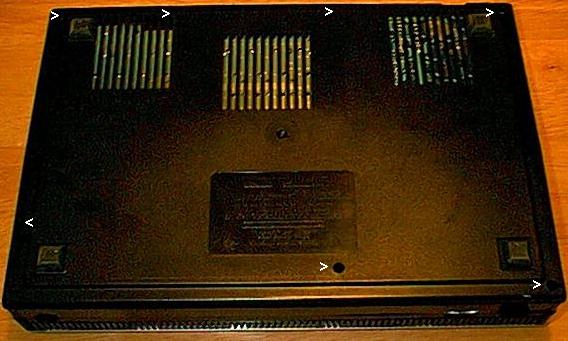
Disconnect all cables from the console. Flip it on its back.
Remove the seven screws that keep it shut. They are four at the front, and three deeply burried at the back. See picture.
Pull out the main switch. This is actually a piece of plastic that grips the real switch inside the console.
Now you can gently lift the bottom plastic part and set it aside, together with the screws and the main switch.
This will make it much easier to remove the motherboard, so do it even if you do not intend to work on the power supply.
There are two screws to remove, in red in this picture.
The back mains connector is not screwed in, just lift it to free it.
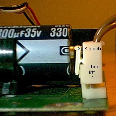
The connection to the motherboard is a bit tricky to remove. There is a self-locking safety plug: to remove it, pinch it, then lift (see picture).
Set aside the power board and its screws (picture).
There are six screws appearant on the metal case. Three serve to fasten it to the plastic top of the console, three keep it together and have a nut on the other side.
Remove the three screws that fasten the metal casing onto the plastic (marked in black in the previous picture), then gently lift the casing. You may encounter a bit of resitance in the area of the cartridge port. This is normal: pull a little to unplug the connector. Do not pull too hard as the keyboard cable is still attached and we don't want to damage it.
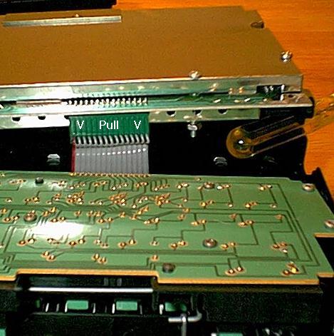
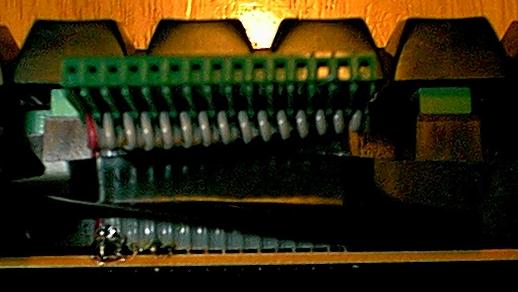
To unplug the keyboard connector, lift the motherboard a little (e.g. with the hangle of a screwdriver, as in the following picture). Then pull down the cable connector. Make sure you don't grab the cable itself, but rather the plastic part of the connector. It may be a bit hard to pull, but this one has no safety lock. Be very carefull when handling the cable, as it is fairly easy to tear it away from the keyboard (if this happens, see below how to fix it). Make a note on which side is which, since it is possible to plug it backwards...
Now you can remove the motherboard, still enclosed in its metal case, and flip it over.
There are two small screws in the middle of the case, that hold a heat sink on top of the VDP (see picture). In some console, there may be a third one that holds a heat sink on top of the clock. Be very gentle while removeing these: unlock both screws first, then proceed to remove them, so that the heat sink won't rotate.
Remove the three screws that hold the case together: a short one and two longer. Store them in a safe place, together with their nuts and locking washers.
Remove the two metal clamps. Note that they are not identical, so make a note of which goes where.
Remove the motherboard from the metal casing. The two metal plates are not identical: make note of which is the top and which is the bottom. Also note which side is left and which is right...
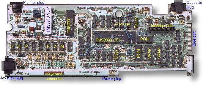
That's it. You've done it. Now you're on your own... All I can offer is a picture to help you identifying the components.
This is only necessary to replace a faulty keyboard. The keyboard connection cable is fairly fragile. If one of the wires gets loose you will notice that a whole row or column of key stops responding. Refer to the following matrix to find out which wire is damaged (the red wire is #15):
            Key                Wire
  =    .   ,   M   N   /        #5
space  L   K   J   H   ;        #4
enter  O   I   U   Y   P        #1
       9   8   7   6   0        #2
fctn   2   3   4   5   1  lock  #7
shift  S   D   F   G   A        #3
ctrl   W   E   R   T   Q        #10
       X   C   V   B   Z        #11
#12   #13 #14 #15  #9  #8  #6
In other words:
 1 Keyboard row 2 (enter O I U Y P)
 2 Keyboard row 3 ( <nc> 9 8 7 6 0)
 3 Keyboard row 5 (shift S D F G A)
 4 Keyboard row 1 (space L K J H ;)
 5 Keyboard row 0 ( =    . , m n /)
 6 Keyboard alpha-lock key
 7 Keyboard row 4 (fctn  2 3 4 5 1 alpha_lock)
 8 Keyboard column 5 ( / ; P 0 1 A Q Z)
 9 Keyboard column 4 ( N H Y 6 5 G T B)
10 Keyboard row 6 (ctrl W E R T Q)
11 Keyboard row 7 (<nc> X C V B Z)
12 Keyboard column 0 (= space enter <nc> fctn shift ctrl <nc>)
13 Keyboard column 1 (. L O 9 2 S W X)
14 Keyboard column 2 (, K I 8 3 D E C)
15 Keyboard column 3 (M J U 7 4 F R V)
Remove the screws that attach the keyboard to the console top. There are two screws on each side. No need to remove the extra screws that are in the middle of the board.
Then lift the keyboard up, duh!
To change a key cap, just pull on it. It should pop up relatively easily. Then you can mix them up and put them back. Great practical joke! Also usefull to learn typing without looking at your keyboard...
To fix a torn cable: use the soldering iron to melt plastic around the wire that is detached at the end of the cable. Then set the board horizontal and deposit a drop of solder on the faulty connection, on the board. Dip the wire in the molten solder and heat it up some more with the iron. Check your work with a continuity tester (or a voltmeter). A good precaution to avoid further problems is to anchor the cable to the side of the keyboard with some electrical tape. Here is a picture, the electrical tape is hard to see (black on black).
Aha! Let's see how many of these screws, nuts and bolts, you'll be able to locate :-)
Put the motherboard back into the metal cases. If you did not mark
which
is which, it may take you a while to figure out how to do that...
Tip #1: the plate with all the bumps in it goes on the components side.
Tip #2: there is a hole for a screw near the side port, in either plate
and in the motherbard: the three holes should align...
Tip #3: the small copper plate, on the side connector, should go inside
the slots on the other part of the casing.
Put back the metal clamps. The one with a flat back goes to the rear, where the metal casing is flush with the motherboard. The one with a slight bend goes in the front, i.e. on the keyboard side.
Put back the three screws that hold the case together. The small one on the connector side, the two long ones at the rear. Remember that washers and the nuts go on the components side of the board.
On the components side, install the small screws that hold the heat sink over the VDP. Make sure both screws are in before you tighten them, so the heat sink won't move around.
Reconnect the keyboard. It is possible to plug it backwards, but this involves twisting the cable, so you should not have too much trouble figuring out which way it goes (red wire to position #1, as marked on the motherboard).
Place the metal casing into the top part of the console. Push down a bit, so that the cartridge connector inserts itself in its plug.
Fasten the three screws that attach the metal casing to the top part of the console.
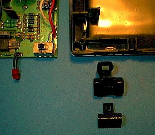
Reconnect the power board. The safety plug can only go in one way. Make sure it clicks in.
When you put the board in place, make sure the LED fits in its place, and that the little piece of plastic that grabs the switch does actually grab it. See picture.
Fasten the power board with its three screws.
Put back the bottom, plastic part and fasten its seven screws. Make sure the little piece of plastic that grips the mains switch is still in place.
Re-insert the main switch, into aforementioned plastic piece.
Put the console back on its feet. Plug it in. If you see smoke coming out of the wents, you messed up. Just kidding: if you worked carefully there is very little risk that you damaged anything (and if you did, I shall not be held liable for it)
Revision 1. 12/10/01. Preliminary. Not for release.