Some Gram cards, like the german 128K GramKarte or the HSGPL card, have the ability to emulate the console GROMs. Because the data bus drivers for the side connector are stronger than real GROMs, the card will allways override console or cartridge GROMs. However, there is a risk that this will end up damaging the GROMs (although it never happened to me).
The obvious solution is to remove the console GROMs. (Note that this will only work with the HSGPL card, since it's the only one with GROM address readback.With the German GramKarte you must leave at least one GROM in the console to keep track of the current address.)
However, removing the GROMs has several drawbacks:.
To overcome these problems, I suggest a very simple solution: install a switch that will disable console and cartrige GROMs so you can use your HSGPL card instead. By just toggling the switch you can go back to the original GROMs.
How does it work
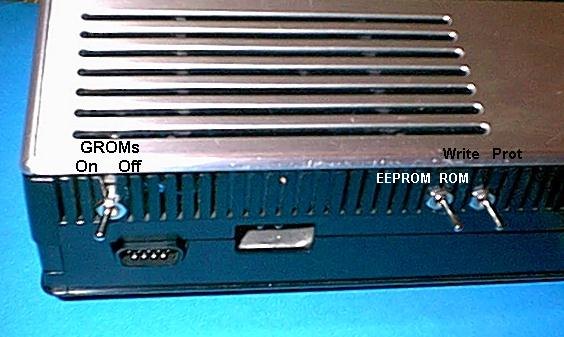
Installing the switch
Testing
The chip that generate the GROM selection signal is a 74LS03 open-collector NAND gate. Its active-high output is then inverted by a 74LS04 to provide the active-low GS* selection signal. It also gates the GREADY line and prevents it from stalling the CPU when the GROMs are not addressed (GROMs set GREADY as "not ready" by default).
74LS138 1K |
Since the 74LS03 has open-collector outputs, it needs a pull-up resistor to +5V. We are going to install an SPDT (single-pole dual-terminal) switch to toggle this resistor between pull-up and pull-down. In the latter position, GROMs cannot be selected any more!
 ,-,-  ,-,-    ===|
 | |   | |     ===| Side connector
 | |   | |     ===|
 | |   | |     ===|
+'-'  +'-'    |    notch
 ,-,-  ,-,-   '-----,
 | |   | |   , ,<-, | <- Cut this end
 | |   | | , R R  R | attach wire to it
 | |   | | R ' '  ' |
+'-'  +'-' '        | Get +5V from any +
        --R--       | ground from any -
                    |
---------------,    |
               |   O|
               |O|
                    ,--------Resistor
Ground ----------o 0_o---------- +5V
When the switch is on the left, GROMs are disabled. When it's on the right, GROMs work as usual.
The easiest way to ensure that the switch works is with my RIP debugger. You can try other debuggers, but many won't work because they call the keyboard scanning routine in the console ROMs and this routine gets the ascii codes from the console GROMs. RIP does its own keyboard scanning and is thus independent of the console GROMs and ROMs. It can be downloaded from here.
To load and run RIP from Extended Basic, type:
CALL INIT
CALL LOAD("DSK1.RIP/O")
CALL LINK("RIP")
From Editor/Assembler, use option 3 to load RIP/O, then run program "RIP".