We all agree that the TI-99/4A is a great machine, but it has its limitations. To some extent, one can overcome these with extra hardware. Sometimes it just implies buying a new card and plugging it in, but sometimes you have to do a modification yourself. And you know what? It's a much more rewarding experience!
This page is meant to introduce you to the art of improving your TI-99/4A. It describes a few modifications, some easy, some more tricky. It also contains primers on how to solder, what chip to use, where to buy them, etc.
So why don't you go ahead and try? The worst that could happen is that you destroy your console (and that's really hard to do), but even if this happens, so what? You can buy another console for less than $20 nowadays...
Basic tools
How to solder
How to make a PCB
Opening the console
Statics
TTL chips
Where to buy?
So you have decided to start improving your TI-99/4A, now is time to select your tools. Some are absolutely required, others will just make your life easier. If you just want to do a quick modification, you probably won't buy the whole lot, but if you are seriously thinking of going the "hardware" way it's worth inversings a few bucks into gool tools...
Required tools
Very useful tools
Optional tools
Here are pictures of (some of) my tools and my workplace. Click on a picture to enlarge it.

Some useful tools. |
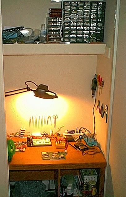
My "magic closet" |

The test station. |
There are very cheap (less than $2) soldering irons. Don't buy those: the tip (aka bit) degrades after a few hours and you'll soon need to buy a new iron! At the other extreme are very expensive (over $200) soldering stations, with temperature control, etc: you don't need those. Just buy a $10-20 iron, 30-40W, with a fine bit.. Try to avoid copper bits.
Once the iron is hot, where do you put it? Not on the table, obviously! An iron stand lets you store the hot iron is a safe place. It generally comprises a small sponge that is used to clean the bit of the iron. Make sure the sponge is wet, then use it to wipe out any solder remains from the iron. You could also make your own stand, with an old hanger and a regular sponge...
There are several types of solder. I prefer a 40% lead 60% tin mix, as it is very fluid and rarely makes bonds between adjacent cupper pads. On the other hand, there are cases when you want to do just that: connect neibouring pads with a solder bridge. For this purpose, I have a roll of 50% lead 50% tin solder that does just fine. In any case, it should have a rosin core flux to help the solder to spread. Remember that lead is TOXIC: do not lick your fingers, nor bite your nails when you're working, do not breath the fumes, and wash your hands with soap once you are done.
For most modifications I used single-conductor, insulated, gauge 30 wire. This is the kind used for "wire-wrap", but it works well for point-to-point soldering. Since it's a small diameter it has a higher resistance (and it's a bit more brittle), so I don't use it for any connection that is suppose to carry a lot of current. For these, typically the power supply and ground lines, I use gauge 26 wire.
Yes, you could use scissors, but the wire may eventually damage them. It is simpler to purchase a small wire cutter. Make sure the tip is really thin, so you can cut off a pin from a chip that's already installed on a board: the "jaws" of the cutter should fit in between two pins.
To solder insulated wire, you must first remove the plastic coating at each end of the wire. Again, you could use scissors and/or your teeth, but a wire stripper makes things easier.
It's like a spring-loaded syringe: you melt solder with the iron, trigger the pump and it sucks the solder in. This tool is optional, but it will make your life way easier... Well worth a few $ investment, in my opinion. You could also go for desoldering braid, but personnally I hate it.
If I ever catch the guy who invented Philips screws, I'll make him eat his invention! There is nothing worse than trying to remove a Philips screw from plastic; and once you have mangled its head, forget it. For this reason, you need a good set of Philips (aka cruciform) screwdrivers, so you can always pick to right one to remove a screw.
Sometimes, your fingers are just too thick! A couple of small pliers, or forceps will come handy. Personnally I prefer forceps, but it's a matter of taste.
A 10x magnifier is usefull to check the quality of your work. If you have money to spend, get a big one, with a stand and a built-in light, so you can work under it. Otherwise, the "jeweller" (that mounts on your glasses), or the "Sherlock Holmes" type will do.
To solder you must hold the iron in one hand, the solder coil in the other... and the wire in the third one! Unless you have an assitant, you will find this little gadget quite usefull. Basically, it consists in several clamps that can be placed in various positions, so as to hold things in place while you solder them.
Always usefull to cut a trace, or clean away excess rosin. My swiss army knife has served several years in this function.
This is a small gadget that lets you verify that two points are indeed connected: it sends a very tiny current (so as not to damage anything) and beeps if it detects a connection. It often is part of a good multimeter. Of course, the multimeter offers more functions: it can measure voltage, current, resistance, frequency, etc. Some fancy models can also test transitors, diodes and capacitors, and report logic states. It's up to you how much you want to invest, but mostly you will need the continuity and the voltage measurement functions.
To solder components (such as a chip, a resistor, a cap, or a piece of wire) on a printed-circuit board:
To connect a wire to a chip that's already soldered on a board (e.g. inside the console), you have the choice bewteen two methods.
Quick and easy method:
Safer but trickier method:
A excellent, more detailed, tutorial on the basics of electronic soldering can be found at www.epemag.wimborne.co.uk/solderfaq.htm Have a look at it, it's worthwhile.
The technique is slightly different for these, because they are so minuscule. But once you get the nack of it, they are actually faster and easier to solder than regular DIP chips.
I have an illustrated guide on how to solder surface mount components here.
For most of the modifications described here, you don't need a printed circuit board (PCB). There are a few, however, where a PCB would be useful, if not required. Unfortunately, this is the most expensive and time-consuming part of the whole process.
There are several solutions, outlined below:
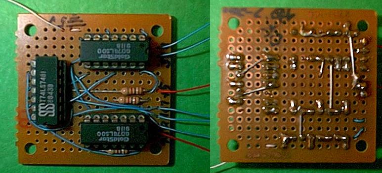
For very simple circuits, you can buy pre-etched, perforated board. These have a grid pattern of perforations, with copper pads on one side. You install the components through the holes, solder them on the pads and build the connections with solder and/or wires. Here is a picture of such a board.
I personnally prefer those that have such a pattern:
| | o-o-o-o | | o-o-o-o | | o-o-o-o | |
| | o-o-o-o | | o-o-o-X | | X-o-o-o | |
| | o-o-o-o | | o-o-o-X | | X-o-o-o | |
| | o-o-o-o | | o-o-o-X | | X-o-o-o | |
You can use the vertical traces for power supply, install the chips across them (see the red X in my example) and you have three pads left to connect wires to the chip pins.
You will note, however, that these perf boards do not come cheap, especially when you want big ones (to make a card that fits in the PE-box, for instance). Also, they do not work well for complex circuits as they tend to turn into a rat's nest of wires, which makes repairs difficult, and is prone to resonnance problems.
The next possibility is to etch your own PCB. The principle is always the same: you buy a copper-clad board (it's not cheap, but not overexpensive either), protect the copper with "something" where you want a pad/trace, and etch the rest of the copper away. Then you have to drill holes within each pad. There are cheap and easy kits to do the etching part, the trick is what to use to protect the copper?
There is etch-resistant ink, but it's a bit messy: it's hard to draw on copper, especially fine lines...
There are stickers, and this is probably the best solution for small boards, but it's tedious work.
You could print out the PCB layout and transfer it to the board with an household iron. There are even special kits for that purpose, although regular laser printer toner will do, when printed on a transparency. You will need a computer program to generate the layout, but there are several freewares on the internet that will do a decent job.
Finally, you could protect the board with a photosensitive resin, irradiate it with UV, digest the resin away, then etch the board. This is the most sophisticated solution and it requires a lot of materials. However there are kits around, and you can buy pre-sensitized boards, ready to be irradiated.
If you have money, you can send your design to a company that will etch (and often drill) the board for you. They will generally require a computer-generated layout, sometimes drawn with their own proprietary software, although they often accept the so-called "Gerber" files supported by most drawing programs.
This solution is generally too expensive for a single prototype, but it may be worthwhile for small series.
I know that the console looks formidable: it's quite intimidating to open this metal shield for the first time. And yet, this is a very straightforward operation. There is no reason why it should be more risky to open a TI-99/4A than a PC.
You will find step by step instructions on how to proceed, together with illustrations, in my "open-console surgery" page.
It is said that static electricity can destroy computer chips and some people are quite paranoid about it. In my experience, there is no need to be too anal retentive, at least not with the kind of chips we have in the TI-99/4A.There are a few rules to follow though:
Be carefull where you put your fingers as you work. As much as possible, do not touch connections unless you need to. Handle chips by their body, not by their pins. Hold printed circuit board by the sides, as you would for a picture on which you don't want to leave greasy fingerprints.
Most modifications decribed in these pages make use of TTL (transistor-transistor logic) chips. These generally have a name starting with 74: for instance 7400, 74138, etc.
This was the original TTL series. Later on, it was superceeded with a better version that used Schottky technology to achieve higher speed and lower power consumption. These chips are labelled 74LS00, 74LS01, etc. They are almost equivalent to the original 74xx series, except for their increased performances. Note that not all 74xx chips have a 74LSxx equivalent, and conversely: many new 74LSxxx were never produced as non-LS chips.
Later on, an Advanced Low-power Schottky series appeared: these are labelled 74ALS00, 74ALS01, etc. Again they are equivalent to the previous two series, except for increased performances. The only difference is that, with the LS series you can connect a pin directly to +5 volts, whereas for the others you should use a pull-up resistor (the same resistor may pull-up a dozen inputs if so desired).
Stay away from the 74HCxx chips. These are not TTL but rather High-speed CMOS chips, functionally equivalent to, but not compatible with the TTL series (unless you know exactly what you are doing). In a matter of gross oversimplification, let's say that CMOS are controlled by voltage, whereas TTL are controlled by current. The big advantage with CMOS is that they don't use any current unless they change state. Which is why a microprocessor heats up when you overclock it: its millions of CMOS gates change state more often, thus use more current, thus generate more heat.
To combine the advantages of CMOS with TTL compatibility, the 74HCTxxx series was produced. These are CMOS chips, but are supposed to be compatible with the regular TTL series. The main point to observe is that any unused input pin MUST be grounded. It's a good practice with TTLs anyhow, but it becomes critical with CMOS chips as an oscillating pin may end up destroying the chip.
You will find the pinouts for some of the most common TTL chips on this page. A more complete list can be obtained from "The Giant Internet IC Masturbator" at http://www.falstaff.demon.co.uk/GIICM.html
You can buy most tools and many components, including TTL chips, at your local electronics store: Fry's, Radio Shack, etc.
Alternatively, you can mail-order what you need. Here are a few places that you may find usefull:
Use the surplus places for things like boards, switches, and tools, for which the main retailers will charge an arm and a leg. TTL chips and memory are generally evenly priced anywhere. The surplus places may also have stocks of obsolete chips, like the memory chips used in the TI-99/4A.
Here is a list of possible modifications to your TI-99/4A. They are rated (somewhat arbitrarily) for difficulty and usefullness. The amount of work required can be estimated from the number of points to solder and/or the components needed.
Difficulty: *. Solder points: 2. Materials: 0. Usefulness: ***
This is a very easy modification: desolder a resistor, solder it back at a different location and you can have two RS232 cards in your PE-box. Even if you have only one such card, it is worth doing the modification, if only to gain confidence. The card will behave exactly as before if it is the only one in the PE-Box. When there are two cards, the modified one answers as RS232/3, RS232/4 and PIO/2.
Difficulty: *. Solder points: 30+. Materials: one 8K EEPROM, one or two switches (optional). Usefulness: **
This modification replaces the DSR ROM with an EEPROM. Since an EEPROM can be written to, you can modify the DSRs and correct potential bugs. In the case of the RS232 card, I wrote a patch that adds extra baud rates (19200 and 38400), handles overclocked consoles and corrects a bug in the interrupt service routine.
The chip is easy to solder in, so this modification is a good project to start with. Possibly just after you modified the RS232 card as described above.
Difficulty: *. Solder points: 3. Materials: 0. Usefulness: **
This modification brings +5 volts to the unused pins in the joystick port. In itself it is not very usefull, but in combination with the joystick adapter board it lets you use "analog" PC joysticks instead of the primitive TI ones. Some third-party joysticks may also require a power supply.
In addition, this modification will force you to break the psychological barrier against opening the TI-99/4A console. I know it's impressive with all its shielding, but it is not any more delicate than a PC or a Mac (rather less, actually).
Difficulty: **. Solder points: 40+. Materials: 1 TTL chip, 5 transistors, 2 capacitors, 1 diode, 8 resistors, 1 LED (optional), 2 connectors (double that for 2 joysticks). Usefulness: **
This mini-board lets you use PC joysticks instead of the TI ones. The advantage is that such joystick is that you can tell how far it was pushed, instead of only on which side it moved.
The board is easy to built, even on a pre-perforated board, but it may also be a perfect occasion to try and etch your first PCB.
Difficulty:**. Solder points:70+. Materials: 4 TTL chips, 5 resistors. Usefulness: **
A simple modification of the Widget allows the 3 cartridges it can hold to be available at the same time, at different GROM bases (e.g. >9800, >9804, and >9810).
Because space is limited inside the Widget, it's better not to use a board, but rather to solder wires directly to the chips. This make it an easier project. Also, since the Widget only contains inert components, the chances to accidentally damage it are extremely low. Modifying the Widget is therefore a good begginer's project.
Difficulty: *. Solder points: 20. Materials: 2 oscillators, 1 resistor. Usefulness: **
This modification gives you the option to overclock the console to 4 MHz instead of 3 MHZ, gaining 33% in execution speed. The speed switching is performed by software (through the CRU), so you can switch back and forth between 3 and 4 MHz depending on your needs.
This is a very simple modification: you desolder 4 components, solder in 3 new components and that's it. The only "difficulty" is that it requires opening the console, but this is trivial (see above).
Difficulty: ** Solder points: 60. Materials: 2 TTL chip. Usefulness: ***
This modification lets you speed up the console multiplexer by placing some (or all) of the wait states it generates under the control of the CRU. As a results, memory operations are as fast in the PE-box as in the console, which means 3 times faster than usual !
The only drawback is that it doesn't work with the original TI 32K memory expansion card (due to its DRAM chips). However, any memory board build around SRAM chips should be ok.
Difficulty: *. Solder points: 30+. Materials: 3 TTL chips. Usefulness: **
The purpose of this modification is to trigger non-maskable interrupts together with normal interrupts. This gives you a much finer control of the interrupt service routine. It's kind of a very specialized mod, but it's easy to do, so it may make a good project for someone who is good at software, but begining in hardware.
Difficulty: **. Solder points: 60+. Materials: Two 8K EEPROMs, one (or two) switch. Usefulness: **
Just like for peripheral cards, it us possible to replace the console ROMs with EEPROM. Except that in this case we'll leave the ROMs in place so the console can still boot if the EEPROMs gets accidentally overwritten. This project is relatively easy, with only two chips to solder in place, although it requires opening the console. It gives you full control over the TI-99/4A operating system, as you can freely alter the EEPROM contents. What's more, the EEPROMs are twice as large as the ROMs, so you can have some nice extra features installed (such as you favorite menu program coming up automatically).
Difficulty: **. Solder points: 30+. Materials: Two TTL chip (expandable to nine). Usefulness: **
Many of the above console modifications are controlled by CRU bits. The drag is that there are only two unused CRU outputs inside the console. This modification is designed to let you install a dedicated CRU interface inside the console, at CRU address >0400. It's useless in itself, but very usefull when combined with some of the above.
The minimal implementation uses two TTL chips and provides 8 output bits, but you can expand it to nine TTL chips and 64 bits (of which 32 can be input, if you so wish).
Difficulty: *****. Solder points: 150+. Materials: 24 chips, caps, resistors, switches, etc. Usefulness: *****
That's one major project: a card that handles IDE hard disk drives. It implies making a printed-circuit board, and soldering quite a bit of chips. But the result is worth the work...
Here is a summary table. Clicking on the links will take you to the page that discusses this modification.
| Modification | Diff | Solder points | Materials | Useful | Description |
|---|---|---|---|---|---|
| 2nd RS232 card | * | 2 | 0 | *** | Changes the CRU address of the card, so you can have two cards in your PE-Box |
| Replacing a card ROM with an EEPROM | * | 30+ | 1 EEPROM (2 switches) |
** | Lest you correct bugs in a card DSRs and/or improve the DSRs |
| Powering the joystick port | * | 3 | 0 | ** | For use with joystick adapters |
| Joystick adapter board | ** | 40+ | 1 chip, 5 transistors, diode, resistors, etc. | *** | Allows to use "analog" PC joysticks |
| Interrupt mod | * | 30+ | 3 chips | * | Renders interrupts non maskable |
| Adding console EEPROMs | ** | 60+ | 2 EEPROMs (2 switches) |
** | Lets you correct bugs in the OS or install an improved OS |
| Multi-bases Widget | ** | 70+ | 4 chips, 5 resistors | ** | Make the 3 cartridges in the Widget appear at the same time, at different GROM bases. |
| Overclocked console | * | 20 | 2 oscillators, 1 resistor | ** | Runs the console at 3 or 4 MHz, selected by software. |
| Wait-states controller | ** | 60 | 2chip | *** | Speeds up 3-fold memory access inside the PE-box. |
| Console CRU interface | ** | 60+ | 2 chips, expandable to 9. | *** | Provides 8 to 64 CRU bits inside the console, to contol the above mods. |
| IDE interface card | ***** | 150+ | 24 chips, 1 large PCB, many passive components | **** | Handles IDE hard drives. |